
In high and extra high voltage transmission systems, capacitor voltage transformers (CVTs) are used to provide potential outputs to metering instruments and protective relays. In addition, when equipped with carrier accessories, CVTs can be used for power line carrier (PLCC) communication.
The details of CVT is given below:-
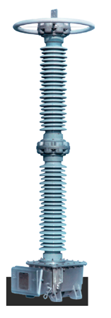
Capacitor stack The capacitor stack is a voltage divider which provides a reduced voltage at the intermediate voltage bushing for a given the voltage applied to the primary terminal. The capacitor stack is a multi-capacitor unit assembly. Each unit is housed in an individual insulator. A cast aluminum cover is on top of the upper capacitor assembly and is fitted with an aluminum terminal. An adapter for mounting a line trap on top of the CVT can be provided with an optional (and removable) HV terminal. The capacitor units are mechanically coupled together by means of stainless steel hardware passing through the corrosion resistant cast aluminum housing. The mechanical connection also establishes the electrical connection between capacitor units. This facilitates field assembly of the CVT.
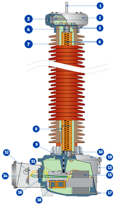

Each capacitor unit is hermetically sealed; a stainless steel diaphragm (expansion bellow) preserves oil integrity by maintaining the hermetic seal while allowing for thermal expansion and contraction of the oil. The capacitor units operate in a practically pressure-free mode over a very wide ambient temperature range. The capacitor stack consists of a series of capacitor elements. The dielectric spacers are a combination of kraft paper and polypropylene film. The ratio of paper/film is carefully determined to provide constant capacitance for a wide range of operating temperature. The aluminum electrodes are precision wound by microprocessor controlled machinery. The capacitor elements are connected with low inductance tinned copper tabs. The stack assemblies are hydraulically compressed and bound with epoxy fiberglass tape to obtain the optimum space factor for capacitance requirement and oil circulation. After assembly in the insulator, 1capacitor units are individually oven dried under vacuum and then impregnated with the processed synthetic oil.
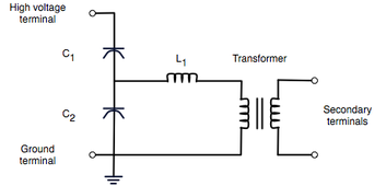
Electromagnetic unit (EMU):- The EMU steps down the intermediate voltage provided by the voltage divider to values suitable for relay and metering applications. A series reactance cancels the phase shift induced during voltage transformation in the capacitor voltage divider. A set of internal taps is used for factory accuracy and phase angle adjustments to provide optimum performance. Over-voltage protection is provided by a protective gap connected in parallel to the series reactances. The inherent capacitance and iron-cored EMU of a CVT require the suppression of Ferro-resonance. The Ferro-resonance suppression device (FSD) contains a saturable The reactor, which acts like a switch, presenting a very high impedance under normal conditions and switching on a damping resistor across the secondary at a prescribed voltage, and switching off the damping load when the voltage has normalized. The voltage sensitive switching strategy effectively suppresses Ferro-resonance without imposing a heavy permanently connected stabilizing burden on the The unit, significantly improving the accuracy and the transient response the performance of the CVT. No field adjustment of the unit is necessary. The EMU is housed in a cast aluminum base tank with a cast aluminum cover. The base tank is filled with treated mineral oil and hermetically sealed from the environment and from the synthetic oil in the capacitor units. A sight glass at the rear of the tank provides for easy oil level monitoring. No oil maintenance is necessary throughout the service life of the unit. An oil drain plug is provided on the base tank.
