The Half wave rectifier is a circuit which converts the ac input voltage to a pulsating D.C voltage. In the Half wave rectifier circuit, a diode is connected in series with a load (RL). The circuit diagram of half wave rectifier is given below.

Where,
Now we discuss, What will happen when the A.C voltage ( Vs ) is applied to the half wave rectifier circuit. During the positive half cycle of A.C supply ( Vs ) the diode D is forward biased that means it conducts, and a current iL will flow through the load RL. And during negative half-cycle ,the diode D, being reverse biased that means it does not conduct , hence no current will flow through the Load (RL). So, iL current flows in one direction and develop output voltage V out which is a pulsating wave of one polarity and is called pulsating D.C voltage. The wave from of the applied voltage Vs and out put voltage V out and current iL is shown in fig.
The current iL in the diode or load RL is given by
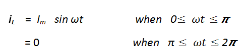
Assuming that the open circuit voltage from the secondary of the transformer is given by
Where, Vm is the peak value of the secondary voltage, the peak value of load current is given.
Where Rf is the dynamic Resistance of the diode.
The average value Iav or the dc value I dc of current through the load RL is given by
The average value or dc value of out put voltage is given by

The rms value of current flowing through the load RL in a Half –wave rectifier is given by –

The pulsating load current iL is the combination of dc and ripple (ac) components. The instantaneous value of the ripple (ac) component i is the difference between the instantaneous value of iL and the dc value of current Idc. Therefore, the instantaneous value of the ripple components is given by--
i=iL - Idc
Therefore , the rms value of the ripple ( ac ) current of Half – wave rectifier is given by.
Therefore,
Similarly,