
Current Transformer is an instrument by which we can easily measure current of high voltage system and also Current Transformer is used for protecting the High voltage line. As long as the current to be measured is small and at low voltage, the direct method of connecting the instruments and relays in the circuits is convenient and adequate. If the currents exceeding several hundreds of amperes have to circulate continuously through the instruments and relays their design becomes more complicated and expensive. Still more difficulties arise when the current to be measured is at a voltage in excess of 1000 volts.
The best solution of these problems is to obtain a copy of the current in the primary circuit and this is achieved with the use of current transformers. A current transformer (C.T) is intended to operate normally with the rated current of the network flowing through the primary winding which is inserted in series in the network. The secondary winding of the current transformer, connected to measuring instruments and relays supplies a current which is proportional to and in phase with the current circulating in the primary winding.

The Current Transformer is similar in construction to the single phase power transformer and the same fundamental laws of the transformer. However, the primary current is not controlled by the power demand in the secondary circuit but is imposed on the transformer by the primary supply system. The primary ampere turns to produce a magnetic flux in the iron core which in turn induces an EMF in the secondary winding; this causes a current to flow through the burden connected to the secondary terminals. At the same time, the ampere turns produced by the secondary current oppose the primary ampere-turns, thus balancing the two ampere turns systems.
The following equation applies to an ideal current transformer:
I1N1=I2N2 Or, I1/I2=N2/N1 Where, N1= Turns in the primary winding N2=Turns in the secondary winding I1= Primary Current I2= Secondary Current
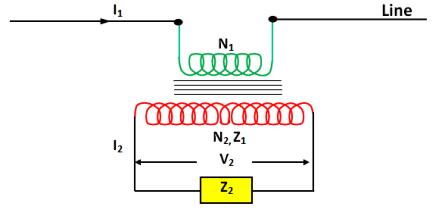
The secondary terminal voltage V2 is controlled by the burden of the transformer, i.e., by the impedance Z2 of the secondary load circuit. i.e., V2= I2Z2 The resistance and leakage reactance of the secondary winding can be combined in the internal impedance Z2 of the transformer. The voltage E2 induced by the magnetic flux must, therefore, exceed the terminal voltage V2 by an amount to compensate for the internal drop.
i.e.,E2 – V2 = E2- I2Z2 = I2Zi or E2 = I2 (Z2 + Zi )
The magnetic flux will thus depend on the secondary voltage E2. This shows that the flux of the C.T and thus also the maximum flux density are variable, a fact of great importance with regard to the operational behavior of the current transformer. This is another point of significance . Whereas the supply conditions control the primary current, the voltage induced in the secondary winding and the flux density of the magnetic core will depend on the secondary current and the load impedance. In actual practice, the condition I1N1 =I2N2 is not fully realized. As in the case of the power transformer, there is always another current I0 called no load current which disturbs this ideal balancing. The emergence of I0 in the case of current, the flux density of the magnetic core will depend on the secondary current and the load impedance.
In actual practice, the condition I1N1 = I1N1 is not fully realized. As in the case of power transformer, there is always another current I0 called no load current which disturbs this ideal balancing. The emergence of I0 in the case of Current transformer is however explained differently from that in the case of a power transformer in which no load current I0 must flow in the primary winding in order to produce the required magnetic flux and to provide for the iron losses . Thus no load current is independent of the secondary current. The primary draws additional current from the supply system so that the primary ampere-turns balance the secondary ampere-turns. In the case of a current transformer, the current of the supply system is flowing in full through the primary winding. A part of this current, called the no-load current , called the no-load current, is consumed to produce the required flux.
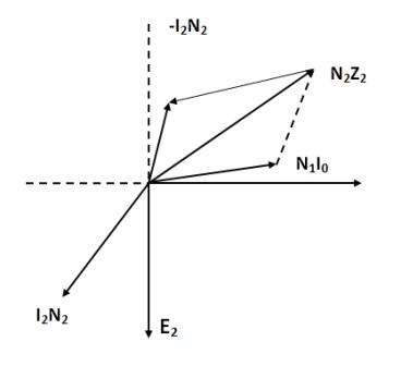
The schematic connection of a current transformer and vector diagram are shown in fig. Current I1 circulated in the primary winding which is connected in series with the lines, the secondary delivers a current I2 to the impedance of the winding and that of the instruments and relays. The vector diagram in fig. shows the functioning of a transformer in which ɸ is the flux common to both windings.This flux ɸ generates EMF E2 in the secondary . And I2 current flows through the impedance Z2 + Zi. This flux is produced by a component of the no load current I0, the vertical component of which accounts for the losses of the transformers. A part of the primary ampere-turns , i.e ,I0N1 are consumed in the excitation of the core , to induce sufficient voltage in the secondary current I2 can be forced through the total secondary impedance Z2+ Zi. The balance ampere turns ( I1 – I0) N1 are now available for transfer to the secondary circuit such that, ( I1 – I0 ) N1 = I2N2 This current I0, is responsible for the different in actual ratio I1/I2 and the displacement in vector N1I1 and – N2I2. These are called the current (or ratio) error and phase error.
Current error is the percentage error in the magnitude of the secondary current given by the formula.

Where , Kn = the rated transformation ratio, Is = the actual secondary current when Ip is flowing in the primary winding, Ip = the actual primary current.
Phase Displacement is different in phase between the primary and secondary current vectors, the direction of the vectors so chosen that the angle is zero for a perfect transformer. The phase displacement is said to be positive when the secondary current vector leads the primary current vector. It is usually expressed in minutes. The burden is the impedance of the secondary circuit expressed in ohms and power factor. The burden is usually expressed as the apparent power in volt-amperes absorbed at a specified power in ohms and power factor. The burden is usually expressed as the apparent power in volt-amperes absorbed at a specified power factor and at the rated secondary current.
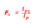
Rated instrument Limit Primary Current is the value of the minimum primary current transformer is equal to or greater than 10 percent, the secondary is equal to or greater than 10 percent, the secondary burden being equal to the rated burden. The composite error should be greater than 10 percent in order to protect the apparatus supplied by the C.T against the high currents produced in the event of the system fault. Instrument Security Factor ( Fs )is the ratio of the instrument limit primary current ( IPL ) to the rated primary current Ip and expressed as,
Composite Error is the RMS value of the difference under steady state condition, integrated over one cycle between,
This is generally expressed as a percentage of the RMS value of the primary current according to the following expression.
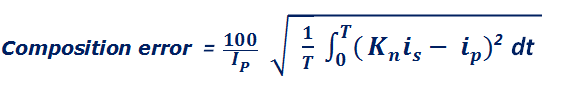
Where Ip = Primary Current T = Duration of the cycle in seconds Kn =Rated transformation ratio Is = Instantaneous value of the secondary current, Ip =instantaneous value of the primary current,
Rated accuracy limit primary current is the value of the highest primary current at which the transformer will comply with the appropriate limit of composite error. It is the product of the rated primary current and the rated accuracy limit factor.
Accuracy limit factor is the ratio of the rated accuracy limit primary current to the rated primary current.
Exciting current is the r.m.s value of the current taken by the secondary winding of a current transformer when the sinusoidal voltage of rated frequency is applied to the secondary terminals, the primary and any other windings being open circuited.
Knee point voltage is the sinusoidal voltage of rated frequency applied to the secondary terminals of the current transformers, all other windings being open circuited, which when increased by 10 percent , causes the exciting current to increase by 50 percent.